
Waveguide WR284 / R32 / WG10

Ta strona dostępna jest również w polskiej wersji językowej

MARKOM Microwaves is a manufacturer of waveguides compliant with the WR284 / WG10 / R32 standard. Basic parameters of WR284 waveguides:

  • operating band: S (per IEEE),
  • frequency range: 2600 ÷ 3950 MHz (2,60 ÷ 3,95 GHz),
  • waveguide attenuation: 0.02–0.014 dB/m, depending on the material used,
  • flange attenuation: 0.02 dB per flange,
  • VSWR: max 1.10,
  • peak power handling: up to 35 MW,
  • average power handling: up to 10 kW,
  • operating pressure for SF6: < 3 bar or vacuum pressure ≥ 1×10⁻³ mbar,
  • internal dimensions: 872.14 × 34.04 mm,
  • waveguide material: aluminum, stainless steel, Cu-ETP copper, OFC copper,
  • wall thickness: ≥3 mm.

Section length, bend type, flange type, material, and surface finish are selected individually, depending on the application and requirements. The peak and average power values given in the datasheets are indicative for the given solution type. Exact values are calculated individually for each waveguide unit supplied.

Typical waveguide applications include linear accelerators (powering accelerating structures, klystrons/magnetrons), weather radars, air traffic control (ATC), long-range maritime radars, satellite and terrestrial communications (tropospheric systems).

Examples of completed projects are available on the Projects page.

WR284 Straight Waveguide

falowod_prosty

Straight sections are manufactured in any length between 50 and 1000 mm. Typical lengths are: 50, 75, 100, 150, 200, 250, 300, 400, 500, 600 mm. Other lengths are made to individual order. Length tolerance ±1 mm. On special order, waveguides are manufactured with a tolerance of ±0.1 mm.

Waveguide material is aluminum (AW-6082), stainless steel (316L), or Cu-ETP copper (CW004A).

Internal waveguide surfaces are left raw or finished according to customer requirements. External waveguide surfaces are left raw or powder-coated.

Waveguides are fitted with CPR284F, CPR284G, MFM32, MFF32 standard flanges. Flanges are made of aluminum (AW-6082), brass (MO58), or stainless steel (316L).

Flange gaskets are made of Viton. Additional gaskets made of conductive silicone are available on request.

Maximum peak and average power depend on the waveguide specification and operating environment. Waveguides are supplied with a document containing the calculated parameters.

Detailed information is provided in the datasheets: WR284-SW-Al | WR284-SW-Cu | WR284-SW-SS

WR284 E-Plane Bent Waveguide
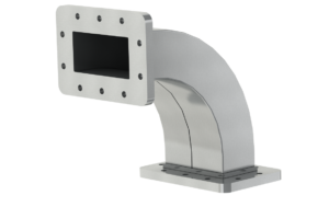
Falowód Kątowy / Angular Waveguide E-Bend

The E-plane bent waveguide is smoothly curved along a defined radius. The E-plane bend changes the direction of the run vertically (up/down).

Typical bend angles are: 30°, 45°, 60°, and 90°. Other bend angles are made to individual order. Bend angle accuracy is 1°.

Typical waveguide dimensions are given in the datasheets. Other arm lengths are set according to individual requirements. Length tolerance is ±1 mm.

Waveguides are made of aluminum (AW-6082), Cu-ETP copper (CW004A), or stainless steel (316L).

Internal waveguide surfaces are left uncoated or finished according to customer requirements. External surfaces are left raw or powder-coated.

Waveguides are fitted with CPR340F, CPR340G, MFM32, MFF32 type flanges. Flanges are made of aluminum (AW-6082), brass (MO58), or stainless steel (316L).

Gasket material is Viton. Additional gaskets made of conductive silicone are available on request.

Maximum peak and average power depend on the waveguide specification and operating environment. Waveguides are supplied with a document containing the calculated parameters.

Details in the datasheets: WR284-RW30E | WR284-RW45E | WR284-RW60E | WR284-RW90E

WR284 Waveguide with Gas Port

A waveguide with a gas port allows connection to an SF₆ insulating gas system. A threaded fitting (e.g. G1/4 or other) is mounted on one wall. Apart from this single feature, the waveguide parameters are identical to a standard WR284. It is manufactured to application requirements: material, wall thickness, surface finish, and flanges.

Sections are produced in lengths from 100 to 1000 mm. Length tolerance ±1 mm. Tolerance of ±0.1 mm is available on special order.

The standard material is aluminium (AW-6061); brass (MO58), Cu-ETP copper, and OFC are available on request. Aluminium waveguides use aluminium flanges (AW-6082), brass or Cu-ETP copper waveguides use brass flanges (MO58), and OFC copper waveguides use stainless steel flanges (316L).

Waveguides are fitted with flanges to the following standards: CPRF32, CPRG32, MFM32, MFF32, LIL. Aluminium waveguides use aluminium flanges (AW-6082). Brass or Cu-ETP copper waveguides use brass flanges (MO58). OFC copper waveguides use stainless steel flanges (316L).

CPRG32 and MFM32 flanges use Viton or conductive elastomer gaskets. LIL flanges use copper gaskets. Gasket materials ensure thermal resistance across the full operating temperature range and the required hermetic seal.

Aluminium waveguide interiors can be left bare or chromate-passivated. Brass or Cu-ETP copper interiors are left bare or silver-plated. OFC waveguide interiors are typically left bare. External surfaces are bare (ground) or powder-coated, regardless of material.