
WR340 Straight Waveguide

Straight sections are manufactured in any length between 50 and 1000 mm. Typical lengths are: 50, 75, 100, 150, 200, 250, 300, 400, 500, 600 mm. Other lengths are made to individual order. Length tolerance ±1 mm. On special order, waveguides are manufactured with a tolerance of ±0.1 mm.
Waveguide material is aluminum (AW-6082), stainless steel (316L), or Cu-ETP copper (CW004A).
Internal waveguide surfaces are left raw or finished according to customer requirements. External waveguide surfaces are left raw or powder-coated.
Waveguides are fitted with CPR340F, CPR340G, FDP26, FDM26 standard flanges. Flanges are made of aluminum (AW-6082), brass (MO58), or stainless steel (316L).
Flange gaskets are made of Viton. Additional gaskets made of conductive silicone are available on request.
Maximum peak and average power depend on the waveguide specification and operating environment. Waveguides are supplied with a document containing the calculated parameters.
Detailed information is provided in the datasheets: WR340-SW-Al | WR340-SW-Cu | WR340-SW-SS
WR340 E-Plane Bent Waveguide
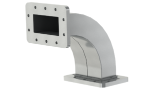 The E-plane bent waveguide is smoothly curved along a defined radius. The E-plane bend changes the direction of the run vertically (up/down).
Typical bend angles are: 30°, 45°, 60°, and 90°. Other bend angles are made to individual order. Bend angle accuracy is 1°.
Typical waveguide dimensions are given in the datasheets. Other arm lengths are set according to individual requirements. Length tolerance is ±1 mm.
Waveguides are made of aluminum (AW-6082), Cu-ETP copper (CW004A), or stainless steel (316L).
Internal waveguide surfaces are left uncoated or finished according to customer requirements. External surfaces are left raw or powder-coated.
Waveguides are fitted with CPR340F, CPR340G, FDP26, or FDM26 type flanges. Flanges are made of aluminum (AW-6082), brass (MO58), or stainless steel (316L).
Gasket material is Viton. Additional gaskets made of conductive silicone are available on request.
Maximum peak and average power depend on the waveguide specification and operating environment. Waveguides are supplied with a document containing the calculated parameters.
Details in the datasheets: WR340-RW30E | WR340-RW45E | WR340-RW60E | WR340-RW90E
WR340 Launcher
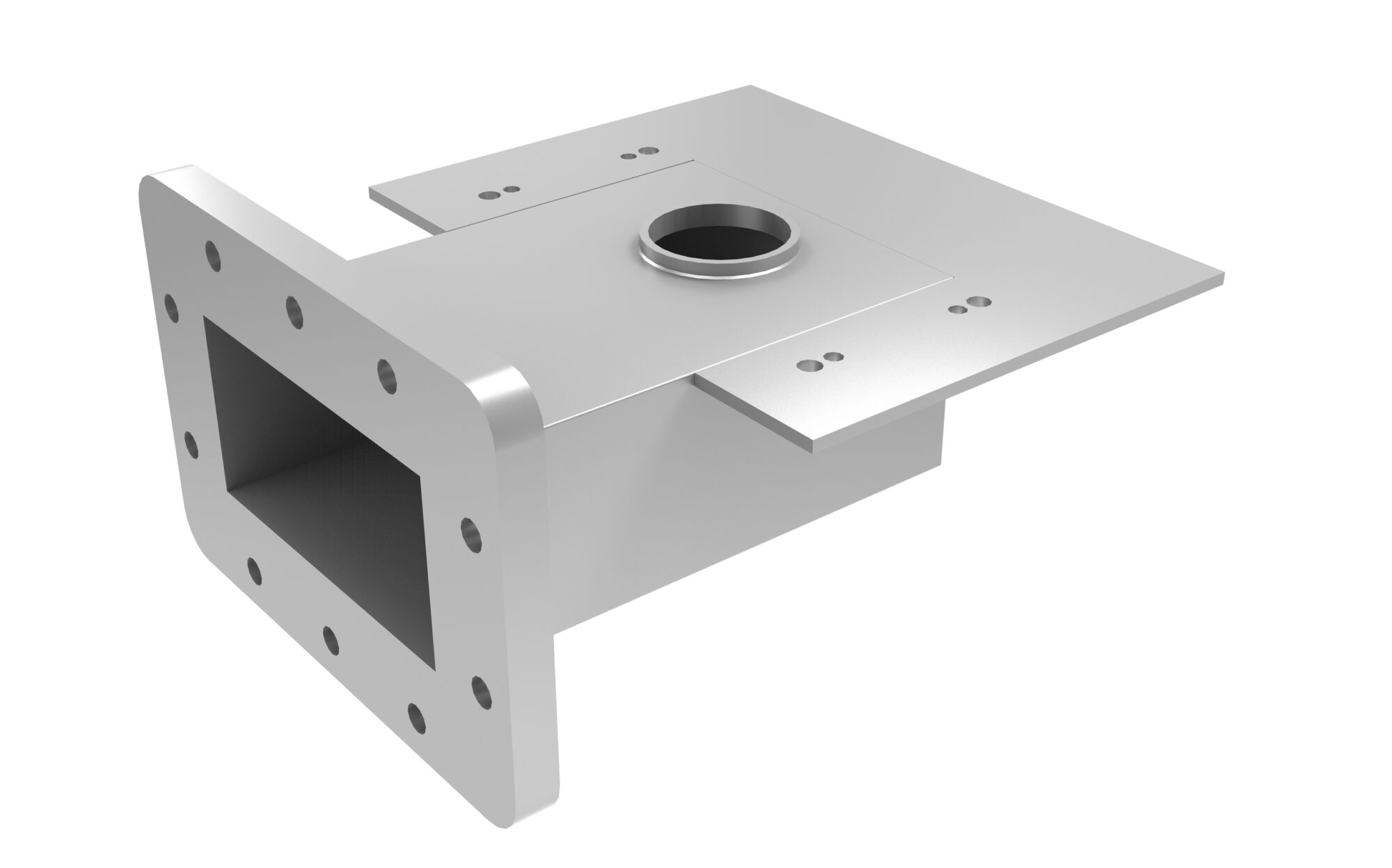
The launcher is a short section of waveguide to which the microwave magnetron is attached. It connects the magnetron to the waveguide assembly and is responsible for efficient transfer of microwave energy. MARKOM manufactures launchers for CW magnetrons rated at 1.5 / 3 / 6 / 10 kW.
The geometry, dimensions, and material of the launcher are matched to the magnetron power, type, and application. The standard material is aluminium (AW-6082); stainless steel (316L) is available on special order.
The standard flange is CPRF26 (no gasket). Other flange types are available on request. Additional flange sealing is also available, protecting the waveguide interior from contamination and microwave leakage.
The launcher interior can be left untreated, coated with SurTec 650, or chromated. The external surface is left untreated (ground finish) or powder-coated.
WR340 Waveguide Window
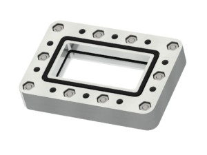
A component that separates two environments while maintaining continuity of the microwave path. Used to maintain vacuum or insulating gas (SF6, nitrogen, dry air) in the waveguide, isolate a chemically aggressive process chamber, or protect the system from the external environment.
Applications include plasma torches (low-pressure plasma generation systems), vacuum dryers (for drying temperature-sensitive products), chemical reactors (supporting production processes or research), and controlled-atmosphere chambers (providing defined process conditions).
MARKOM waveguide windows are hermetically sealed across a pressure range from 1×10⁻³ mbar to 2 bar, operate at temperatures from −30 to +150°C, and handle microwave power up to 6 kW. Compatible with WR340 standard waveguides.
Flange material is aluminium (AW-6082); stainless steel (316L) is available on request. The barrier is made of quartz glass (high-purity fused silica). Gaskets are made of Viton (fluoroelastomer), providing high chemical and thermal resistance.
Full specifications are given in the Datasheet.
Coupler WR340 with VSWR Meter
VSWR (voltage standing wave ratio) indicates the impedance match between the waveguide assembly and the process chamber. Monitoring VSWR allows assessment of the system's energy efficiency and measurement of reflected power, reducing the risk of magnetron failure.
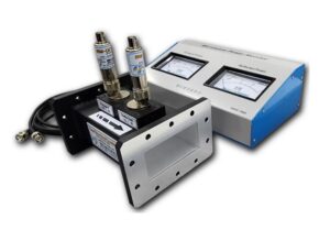
MARKOM offers a complete set: a waveguide dual directional coupler with precision sampling probes and an analogue meter. The set enables simultaneous measurement of forward and reflected power.
Construction:
- Power measurement range: up to 3 kW, readout resolution 100 W
- Waveguide and flange type: WR340 or WR430
- Readout: analogue meter
- Cables connecting coupler to meter: coaxial, 1 m length