Waveguide WR340 / WG9A / R26

- Operating band: S (IEEE) / E (NATO)
- Frequency range: 2200–3300 MHz
- Materials: aluminum (Al), copper (Cu-ETP)
- Waveguide attenuation: 0.01–0.04 dB/m (unfinished surfaces)
- Peak power capability: max. 15 MW (unfinished surfaces)
- Internal dimensions: 86.36 × 43.18 mm
Waveguide WR284 / WG10 / R32
- Operating band: S (IEEE)
- Frequency range: 2600 – 3950 MHz
- Materials: aluminum (Al), brass (Br), copper (Cu-ETP), copper (OFC)
- Waveguide attenuation: 0.02 – 0.035 dB/m (unfinished surfaces)
- Peak power capability: max. 25 MW (unfinished surfaces)
- Internal dimensions: 72.14 × 34.04 mm
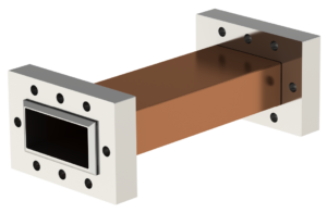
Waveguide Transitions and Tapers
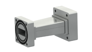
In microwave systems, changes in waveguide standard, cross-section or profile are often required:
- In low-pressure plasma generation systems, reducing the waveguide profile (tapered waveguide) increases plasma excitation efficiency
- In industrial production lines, waveguides of different standards can be matched without impedance disruption or energy loss, maintaining continuity of the waveguide assembly
Construction:
We design and manufacture waveguide transitions for multiple standard pairs (e.g. WR430→WR340 or WR340→WR284). The primary material is aluminium AW-6082; brass, stainless steel and oxygen-free copper are available on request. Components are precision-milled, ground and polished. Joining method is selected according to the application — vacuum, pressure or high-power transmission.
Peak and Average Power Calculation
 Catalogue parameters define waveguide performance under reference conditions. MARKOM determines peak and average power limits using a proprietary calculation tool. Input data includes:
- internal dimensions, wall thickness, section length
- operating frequency, VSWR, pulse width, pulse repetition rate
- materials, internal and external surface finish, roughness, attenuation, thermal emissivity
- flange type, quantity, insertion loss
- insulating gas type, operating pressure, vacuum level
- ambient temperature, wall temperature, pulse ΔT
- waveguide orientation, list of heat-dissipating surfaces
- cooling method
Four criteria are evaluated simultaneously: pulse heating of the surface layer, steady-state thermal balance, dielectric breakdown of the medium, and multipactor risk.
Sample calculation output:
The limiting factor is the steady-state thermal balance. A very small ΔT severely restricts power – a larger temperature margin will yield significantly higher results.