
Straight WR975 Waveguide
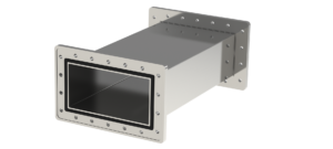
Single straight sections are manufactured in any length from 50 to 600 mm. Typical dimensions are: 50, 75, 100, 150, 200, 250, 300, 400, 500, 600 mm. Sections can be joined into custom lengths, made to individual order. Length tolerance ±1 mm.
Waveguide material is aluminum (AW-6082) or stainless steel (316L).
Solely for the purpose of comparing mechanical, electrical, and power-handling parameters, all waveguide types are assumed to have unfinished internal and external surfaces.
In practice, surface finish is selected based solely on user requirements, environmental conditions, and the application the waveguides will operate in. Internal surfaces may, for example, be passivated, while external surfaces may be powder-coated.
Waveguides are fitted with CPR975F, CPR975G, FDP9, and FDM9 standard flanges. Flanges are made of aluminum (AW-6082) or stainless steel (316L).
Flange gaskets are made of Viton. Additional gaskets made of conductive silicone are available on request.
Maximum peak and average power depend on waveguide specification and operating environment. Calculated parameter data is provided with the waveguide.
Detailed information is available in the datasheets: WR975-SW-Al | WR975-SW-SS
WR975 Waveguide, E-Plane Bend
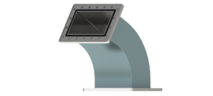 The waveguide is smoothly bent along an arc of specified radius in the E-plane. The E-plane bend changes the route direction vertically (up/down).
Typical bend angles are: 30°, 45°, 60°, and 90°. Other angles are made to individual order. Bend angle accuracy is 1°.
Typical waveguide dimensions for a given bend angle are provided in the datasheets. For waveguides with extended arms, arm lengths are determined individually with a tolerance of ±1 mm.
Waveguides are made of aluminum (AW-6082) or stainless steel (316L).
Internal waveguide surfaces are left unfinished or finished according to user requirements. External surfaces are left unfinished or powder-coated.
Waveguides are fitted with CPR975F, CPR975G, FDP9, or FDM9 flanges. Flanges are made of aluminum (AW-6082) or stainless steel (316L).
Gasket material is Viton. Additional gaskets made of conductive silicone are available on request.
Maximum peak and average power depend on waveguide specification and operating environment. Calculated parameter data is provided with the waveguide.
Details in the datasheets: WR975-RW30E | WR975-RW45E | WR975-RW60E | WR975-RW90E