
Rectangular waveguides

Most commonly selected standards:
Other standards available on request. For every available standard we offer straight sections (SW), bent waveguides (RW), and bent waveguides with long arms (LS).
Straight Sections (SW)
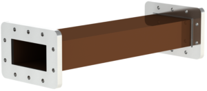
Straight sections are available, selected according to the standard. On request, we manufacture sections of any length in the range of 50 to 600 mm. The most commonly selected lengths are 50, 100, 150, 200, 250, 300, 400, 500, and 600 mm.
Typical manufacturing accuracy is +/- 1 mm. Sections with an accuracy of +/- 0.1 mm can also be manufactured.
Bent Waveguides in the E-plane (RW)
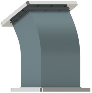
A waveguide bent in the E-plane is smoothly curved along a defined radius. The E-plane changes the direction of the path vertically (up/down).
The most commonly selected bend angles are 30, 45, 60, or 90 degrees. On request, we manufacture bends at any angle with an accuracy of +/- 1 degree.
When selecting the bend radius, we follow the "rule of thumb." The bend radius depends on the waveguide standard, operating frequency, and the application in which the waveguide is used. On request, we manufacture waveguides bent at a selected radius.
Bent Waveguides in the E-plane with Long Arms (LS)
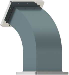
A waveguide bent in the E-plane with long arms is smoothly curved along a defined radius. The most commonly selected bend angles are 30, 45, 60, or 90 degrees. On request, we manufacture bends at any angle with an accuracy of +/- 1 degree.
As with bent waveguides (RW), when selecting the bend radius, we follow the "rule of thumb." The bend radius depends on the waveguide standard, operating frequency, and the application in which the waveguide is used. On request, we manufacture waveguides bent at a selected radius.
Unlike "RW" waveguides, the arms of "LS" waveguides can be extended. The arm lengths do not need to be symmetrical. On request, we manufacture waveguides with the selected arm length. Typical manufacturing accuracy is +/- 1 mm.
Waveguide Transitions and Tapers
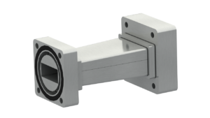
In microwave systems, changes in waveguide standard, cross-section or profile are often required:
- In low-pressure plasma generation systems, reducing the waveguide profile (tapered waveguide) increases plasma excitation efficiency
- In industrial production lines, waveguides of different standards can be matched without impedance disruption or energy loss, maintaining continuity of the waveguide assembly
Construction:
We design and manufacture waveguide transitions for multiple standard pairs (e.g. WR430→WR340 or WR340→WR284). The primary material is aluminium AW-6082; brass, stainless steel and oxygen-free copper are available on request. Components are precision-milled, ground and polished. Joining method is selected according to the application — vacuum, pressure or high-power transmission.
Peak and Average Power Calculation
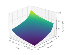 Catalogue parameters define waveguide performance under reference conditions. MARKOM determines peak and average power limits using a proprietary calculation tool. Input data includes:
- internal dimensions, wall thickness, section length
- operating frequency, VSWR, pulse width, pulse repetition rate
- materials, internal and external surface finish, roughness, attenuation, thermal emissivity
- flange type, quantity, insertion loss
- insulating gas type, operating pressure, vacuum level
- ambient temperature, wall temperature, pulse ΔT
- waveguide orientation, list of heat-dissipating surfaces
- cooling method
Four criteria are evaluated simultaneously: pulse heating of the surface layer, steady-state thermal balance, dielectric breakdown of the medium, and multipactor risk.
Sample calculation output:
The limiting factor is the steady-state thermal balance. A very small ΔT severely restricts power – a larger temperature margin will yield significantly higher results.